Lesson 03: Initial main.c
Triangle Fill
Why rasterizers use triangles
Triangles have several advantages over more complex polygons. The three points of a triangle always lie on a single plane (coplanar) while polygons with more vertices do not have this advantage and aren’t guaranteed to be flat. Each point on a triangle has the same surface normal, which is a highly useful property in 3D rendering as we’ll see.
Triangles are also always convex, which means a horizontal scanline can intersect it at most at two edges which makes finding and filling spans between surface edges far more simple. For our purposes, this is the most essential property of triangles. An n-gon is just a polygon with more than 3 sides. A scanline can intersect n-gons at more than two edges, resulting in multiple disconnected spans on the same row. To draw pixels on each disconnected span for that polygon would require sorting them and deciding which pairs of intersection points to fill, greatly increasing the complexity of the algorithm. Instead, any n-gon can be converted into triangles on export from a 3D modeling program, or even by us at runtime when loading from a file. Modern GPUs still work exclusively using triangle rasterization. We’ll revisit each of these properties as we build the rasterizer.
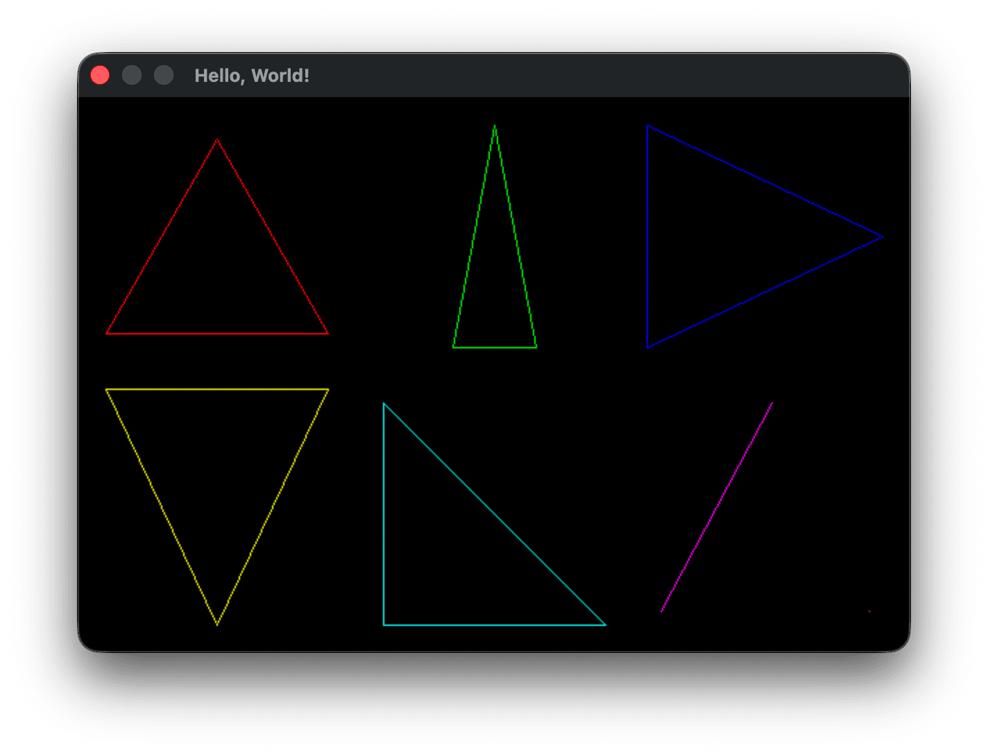
We left off having drawn the outline of triangles to the screen using our drawLine function to interpolate the position of each pixel on the line between two points. We’ve also talked about the scanline rasterization process used to render an image to a CRT screen and how triangles have the advantage of allowing us to easily find and fill the span between the two edges crossing the scanline. The algorithm we’ll use is just that easy: we iterate from the top of a triangle to the bottom, finding where the edges of the triangle cross the current scanline, and filling the gap between the two edges - the span. A triangle is thus filled from top to bottom, with each horizontal span filling from the left edge to the right.
Adding Vec2 type
The way we’re representing points currently is not very convenient to work with. For each edge we’re passing drawLine four values representing the x and v positions of both edges in screen space. And as we’ve noted, in screen space we’ve set the origin to the top-left of the screen where the first pixel of our framebuffer is, and unlike in the typical Cartesian system, y grows downward not upward. The traditional approach to storing and passing point coordinates is to use what is known as a vector. Vector might be one of the most overloaded words in the English language, but at its simplest we can just think of it as a Cartesian (x, y) coordinate. Later on we’ll build on that notion, but for now we can define a vector as:
uint32_t buffer[WIDTH * HEIGHT];

typedef struct Vec2 {
    int x;
    int y;
} Vec2;
Adding drawTriangle()
We can then change our drawLine function signature to take two Vec2 objects by reference instead of four int objects by value. We won’t need to change their values, so we can declare them const. We can either replace all uses of x0, y0, x1 and x2 inside drawLine with v0->x, v0->y, v1->x and v1->y or create convenience pointers as I’ve done here. With the const hint to the compiler and with optimizations on, the compiler should optimize the code into the same thing aside from the signature differences.
void drawLine(const Vec2 *v0, const Vec2 *v1, uint32_t color) {
    int x0 = v0->x, y0 = v0->y;
    int x1 = v1->x, y1 = v1->y;
After drawLine and before main I defined a new function drawTriangle:
void drawTriangle(const Vec2 *tri, uint32_t color) {
    drawLine(&tri[0], &tri[1], color);
    drawLine(&tri[1], &tri[2], color);
    drawLine(&tri[2], &tri[0], color);
}
And inside main changed our drawLine calls into const Vec2 array definitions and calls to drawTriangle:
        .buf    = buffer
    };

    // x-dominant (wide/flat)      — top-left cell
    const Vec2 tri0[] = { { .x =  20, .y = 170 },   // bottom-left
                          { .x = 180, .y = 170 },   // bottom-right
                          { .x = 100, .y =  30 } }; // top-middle
    // y-dominant (tall/narrow)    — top-middle cell
    const Vec2 tri1[] = { { .x = 270, .y = 180 },   // bottom-left
                          { .x = 330, .y = 180 },   // bottom-right
                          { .x = 300, .y =  20 } }; // top-middle
    // one vertical edge           — top-right cell
    const Vec2 tri2[] = { { .x = 410, .y =  20 },   // top-left
                          { .x = 410, .y = 180 },   // bottom-left
                          { .x = 580, .y = 100 } }; // right-middle
    // one horizontal edge         — bottom-left cell
    const Vec2 tri3[] = { { .x =  20, .y = 210 },   // bottom-left
                          { .x = 100, .y = 380 },   // top-middle
                          { .x = 180, .y = 210 } }; // bottom-right
    // right triangle              — bottom-middle cell
    const Vec2 tri4[] = { { .x = 220, .y = 220 },   // top-left
                          { .x = 220, .y = 380 },   // bottom-left
                          { .x = 380, .y = 380 } }; // bottom-right
    // degenerate: two coincident vertices  — bottom-right cell
    const Vec2 tri5[] = { { .x = 500, .y = 220 },   // top-right
                          { .x = 500, .y = 220 },   // top-right
                          { .x = 420, .y = 370 } }; // bottom-left
    // degenerate: single point    — tucked in corner of bottom-right cell
    const Vec2 tri6[] = { { .x = 570, .y = 370 },
                          { .x = 570, .y = 370 },
                          { .x = 570, .y = 370 } };
    drawTriangle(tri0, colors[RED]);
    drawTriangle(tri1, colors[GREEN]);
    drawTriangle(tri2, colors[BLUE]);
    drawTriangle(tri3, colors[YELLOW]);
    drawTriangle(tri4, colors[CYAN]);
    drawTriangle(tri5, colors[MAGENTA]);
    drawTriangle(tri6, colors[ORANGE]);

    // Open a system window using the given window specifications
    if (fenster_open(&window) < 0) return 1;
We’re back to drawing our example triangles exactly as we started the lesson. What have we gained? We can now pass vertex information around in a more convenient fashion, but also have a better abstraction layer, passing each Vec2 array of triangle vertices to drawTriangle. Within drawTriangle we now need to find and fill all of the spans where the triangle crosses the spanline. At the least, we need to know the vertical screen space height of the triangle so that we can iterate over each scanline that touches the triangle.
The easiest way to find the minimum and maximum of three integer values is to create a few helper functions, int_min and int_max, both declared to be static inline. inline tells the compiler to replace the function calls with their bodies at each occurence, avoiding the added overhead of calling a function. For small functions like this the compiler will carry out that optimization by itself, but it’s good practice to provide those hints to the reader and the compiler. static tells the compiler that the function symbol is only accessible from this file.
Before drawLine and after the Vec2 definition:
// Utility math functions
static inline int int_max(int x, int y) {
    return (x > y) ? x : y;
}

static inline int int_min(int x, int y) {
    return (x > y) ? y : x;
}
and we replace drawTriangle with:
void drawTriangle(const Vec2 *tri, uint32_t color) {
    const Vec2 *a = &tri[0], *b = &tri[1], *c = &tri[2];

    // Find the vertical span of the triangle, clamp to vertical screen bounds
    int top_y = int_max( int_min(a->y, int_min(b->y, c->y)), 0 );
    int bot_y = int_min( int_max(a->y, int_max(b->y, c->y)), HEIGHT - 1);
}
I set up a few convenience pointers to each tri vector, then calculate the y boundaries of tri. top_y holds the smallest value among v0->y, v1->y and v2->y clamped to 0, bot_y holds the greatest value of those same components clamped to the screen height. Now we need to iterate over every scanline between top_y and bot_y inclusive. We need to find a clean interface for finding the x values of any intersections of the triangle against the scanline. We need a helper function that takes the triangle vertices representing an edge, and tell us if that edge crosses the scanline, and returning the x value of that intersection if it exists. This helper function might be called hundreds of thousands of times per frame depending on the number of triangles being rendered, so we’ll declare it static inline also:
static inline bool crossesScanlineAt(const Vec2 *v0, const Vec2 *v1, int scanline_y, int *x) {
    ...
}
If the edge crosses scanline_y we set the x value and return true otherwise we return false. Given what we have learned while implementing drawLine, you should be able to see an easy solution for determing that x value. I would recommend taking the time now to implement your own solution before reading on.
You might have noticed that we can use the basic interpolation algorithm we developed in drawLine to find the x intersection. There are several edge cases to consider. When dy is 0, the edge is horizontal. Our scanline fill algorithm as we proposed will fill between two x-values. For a horizontal line, crossesScanlineAt can’t tell us anything valuable. The horizontal line will eventually be filled when crossesScanlineAt iterates over the other two edges of the triangle that do cross the scanline. The other edge case is when scanline_y lies above or below the y values of the edge passed to crossesScanlineAt. In both cases we exit early returning false.
static inline bool crossesScanlineAt(const Vec2 *v0, const Vec2 *v1, int *x, int scanline_y) {
    int dy = v1->y - v0->y;
    if (dy == 0) return false; // The edge is a horizontal line or coincident - no crossing

    if (scanline_y < int_min(v0->y, v1->y) || scanline_y > int_max(v0->y, v1->y))
        return false; // Ensure that the current scanline is between the two edge vertices

    int dx = v1->x - v0->x;
    float t = (float)(scanline_y - v0->y) / (float)dy; // Progress along y: 0 at v0->y, 1 at v1->y
    *x = (int)(v0->x + t * dx + 0.5f); // Interpolated x at this y, rounded

    return true;
}
This tells us if and where an edge crosses the current scanline y-axis. Inside drawTriangle we need to check each edge for intersection and decide what the left and right bounds of our horizontal span will be:
static inline void updateSpan(int x, int *left_x, int *right_x) {
    if (x < *left_x) *left_x = x;
    if (x > *right_x) *right_x = x;
}

void drawTriangle(const Vec2 *tri, uint32_t color) {
    const Vec2 *a = &tri[0], *b = &tri[1], *c = &tri[2];

    // Find the vertical span of the triangle, clamp to vertical screen bounds
    int top_y = int_max( int_min(a->y, int_min(b->y, c->y)), 0 );
    int bot_y = int_min( int_max(a->y, int_max(b->y, c->y)), HEIGHT - 1);

    // Loop over each scanline in the vertical span, find then fill its horizontal span
    for (int scan_y = top_y; scan_y <= bot_y; scan_y++) {
        // Keep track of the current x bounds of any crossing edges
        int left_x = INT_MAX, right_x = INT_MIN, x;

        // Update the current horizontal span
        if (crossesScanlineAt(a, b, scan_y, &x)) updateSpan(x, &left_x, &right_x);
        if (crossesScanlineAt(b, c, scan_y, &x)) updateSpan(x, &left_x, &right_x);
        if (crossesScanlineAt(c, a, scan_y, &x)) updateSpan(x, &left_x, &right_x);

        // Fill the current span, clamp to horizontal screen bounds
        for (int scan_x = int_max(left_x, 0); scan_x <= int_min(right_x, WIDTH - 1); scan_x++) {
            PIXEL(scan_x, scan_y) = color;
        }
    }
}

Degenerate triangles
We now have our filled triangles. You might notice the single orange pixel triangle with all three vertices coincident did not render. These types of triangles are called degenerate where two of the vertices are coincident or all three are colinear (in a straight line). You can generally assume that any triangle definition loaded from a 3D file format like Wavefront OBJ and glTF will not contain degenerate triangles. However, as you transform the position of geometry by moving the camera in a 3D engine, it’s possible to end up viewing triangles edge on and the renderer will occasionaly be passed such degenerate zero area triangles. It’s up to the engine to decide whether to render degenerate lines with no area as a single pixel or a single edge, or to skip rendering them altogether. Here are four additional triangles to further test that everything is rendering as we expect. Two of the triangles are valid and are either 2 pixels wide or tall, two others are either 1 pixel wide or tall degenerate triangles with no area:
    // degenerate: single point    — tucked in corner of bottom-right cell
    const Vec2 tri6[] = { { .x = 570, .y = 370 },
                          { .x = 570, .y = 370 },
                          { .x = 570, .y = 370 } };
    // near-horizontal sliver      - left-side middle
    const Vec2 tri7[] = { { .x =  20, .y = 195 },   // left
                          { .x = 180, .y = 195 },   // right
                          { .x = 180, .y = 194 } }; // 1 pixel above right
    // near-vertical sliver        - bottom-left between yellow and cyan tris
    const Vec2 tri8[] = { { .x = 200, .y = 210 },   // top
                          { .x = 200, .y = 380 },   // bottom
                          { .x = 201, .y = 295 } }; // middle, 1 pixel right
    // degenerate: horizontal line - in the middle between green and cyan tris
    const Vec2 tri9[] = { { .x = 240, .y = 200 },   // left
                          { .x = 310, .y = 200 },   // middle
                          { .x = 380, .y = 200 } }; // right
    // degenerate: vertical line   - bottom-right between cyan and magenta tris
    const Vec2 tri10[] = { { .x = 400, .y = 220 },   // bottom
                           { .x = 400, .y = 380 },   // top
                           { .x = 400, .y = 300 } }; // middle
...
    drawTriangle(tri6, colors[ORANGE]);
    drawTriangle(tri7, colors[PURPLE]);
    drawTriangle(tri8, colors[WHITE]);
    drawTriangle(tri9, colors[GRAY]);
    drawTriangle(tri10, colors[SILVER]);

All of the new triangles render as expected except the horizontal degenerate triangle tri9, along with the three coincident vertices triangle tri6 that wasn’t rendering previously. For both, in all three crossesScanlineAt checks the dy value is 0 and return false so that in drawTriangle, left_x is still INT_MAX and right_x is still INT_MIN, and scan_x in the fill loop never passes the conditional check scan_x <= int_min(right_x, WIDTH - 1).
The process of choosing triangles to ignore drawing is called culling. Culling can be used to maintain visual correctness, and can also be used to reduce the number of computations carried out in the rendering pipeline by removing unviewable geometry. We’ll revist culling later as it becomes more important in our rendering pipeline.
For now, a simple check that would handle rejecting drawing all forms of degenerate triangle cases would be to cull any triangle with no area. The naieve area = 1/2 * base * height formula is relatively expensive in terms of CPU instruction cycles, requiring several square root and divide instructions, which can take somewhere around 40-60 cycles on a modern processor. A much cheaper method that gives us the same information is to find the cross product of two triangle vectors. “Clocking” in at 2 multiplies and 5 subtracts this method is far more efficient, and can take somewhere between 3-10 total instruction cycles. The cross product is primarily useful in graphics programming because it gives us the surface normal of two vectors, which is a vector perpendicular to the plane the two vectors share. The normal is used for computing things like lighting intensity and whether hidden surfaces should be rendered or not (backface culling). For now we’re only interested in using the cross product formula to derive the area of our triangle.
Using cross product to determine area
When you take the cross product of two 2D vectors, the resulting vector is a “3D” vector that looks like (0, 0, z) where the z (depth) component value is twice the area of the triangle formed by edges of the two vectors. (0, 0, z) also is perpendicular to the plane containing the first two vectors at their shared origin. This is not the usual way the cross-product is introduced, but I think it’s a more intuitive introduction. We’ll derive the cross product formula properly later, but for now it’s given as:
u × v = (u.y*v.z - u.z*v.y, u.z*v.x - u.x*v.z, u.x*v.y - u.y*v.x)
Where u and v are two vectors of the form (x, y, z). The multiplication symbol used in u × v denotes the cross product of two vectors, which is not the same as the times symbol used to indicate multiplying two scalar values together. The video below walks through how to arrive at the area of a triangle using the cross product definition.
I’ll work through the steps in the video, using the general 3D cross product formula to arrive at the general cross product formula for two 2D vectors u and v:
u × v = (0, 0, u.x*v.y - u.y*v.x)
As we’ll see, the z value u.x*v.y - u.y*v.x is a scalar that represents twice the area of the triangle built on vectors u and v, which we derive from our existing position vectors from the origin a, b and c. We could try picking two of these original position vectors a, b and c and applying the cross product to them, but the resulting area derived from the cross product would be with respect to the triangle formed with b and c and the origin and not the triangle formed by a b and c. Looking at the video above, if we used the current vectors b and c from the origin at (0, 0), they would describe a triangle from the origin with vector a in the middle, not the triangle abc. However, we can derive two displacement vectors from our three positional vectors if we choose one of the vectors a, b, c as a common origin and subtract it from the other two vectors. Looking at the video, we choose vector a as our origin and subtract vector a from vector b to form vector u, and subtract vector a from vector c to form vector v. These two new vectors from the same origin form the edges of the triangle we want.
u = (b.x - a.x, b.y - a.y)
v = (c.x - a.x, c.y - a.y)
and substituting these values of u and v and a z value of 0 for each vector into the general 3D cross product definition gives:
u × v = (u.y*v.z - u.z*v.y, u.z*v.x - u.x*v.z, u.x*v.y - u.y*v.x)
The z values of 0 cancel out the first two terms:
u × v = (u.y*0 - 0*v.y, 0*v.x - u.x*0, u.x*v.y - u.y*v.x)
u × v = (0, 0, u.x*v.y - u.y*v.x)
We can plug the original component values of a, b and c back in replacing the edge components of vectors u and v to express the computation with our original three positional vectors:
u × v = (0, 0, ((b.x - a.x)*(c.y - a.y) - (b.y - a.y)*(c.x - a.x)))
The z-component of the cross product is thus the parallelogram formed by the sides of the triangle u and v:
z = (b.x - a.x)*(c.y - a.y) - (b.y - a.y)*(c.x - a.x)
which is what we wanted to prove. With these two multiplications and five subtractions we’ve computed twice the area of our triangle. We don’t actually need to divide by 2 to get the area of the triangle, we only care that the area is not zero, which means we have a non-degenerate triangle.
Removing degenerate triangles
We can now use the cross product formula for 2D vectors that we just derived to skip drawing any degenerate triangles with an area of 0, such as triangles where two or more vertices are coincident or all three vertices are colineaer (on the same straight line):
void drawTriangle(const Vec2 *tri, uint32_t color) {
    const Vec2 *a = &tri[0], *b = &tri[1], *c = &tri[2];

    // The cross product for 2D vectors has only a z-component: (0, 0, (b-a)×(c-a)).
    // That z value equals the signed parallelogram area spanned by u and v.
    // A value of zero means no area — no triangle to draw.
    // 2D cross product formula: u × v = (0, 0, u.x*v.y - u.y*v.x)
    int crossProductZ = ((b->x - a->x) * (c->y - a->y)) - ((b->y - a->y) * (c->x - a->x));
    if (crossProductZ == 0) return;

    // Find the vertical span of the triangle

This draws all triangles that have a non-zero area, just as we expected. You might wonder, what does it mean for that signed paralellogram area representing the z component of the cross product to be negative or positive? Let’s check by changing our comparison operator:
    int crossProductZ = ((b->x - a->x) * (c->y - a->y)) - ((b->y - a->y) * (c->x - a->x));
    if (crossProductZ < 0) return; // negative signed paralleogram area of u × v

We should see only three triangles with area greater than or equal to 0 render now. Two of our zero area degenerate triangles draw: tri5 and tri10. tri6 and tri9 pass the area check but have dy == 0 as mentioned above and never fill their horizontal spans. But why is tri3 showing up, and why aren’t all of the other filled triangles? This means tri3 has a positive area and the other filled triangles all have negative areas. If you noticed at the end of the video above, the cross product vector that is perpendicular to the triangle abc surface can either point away from the screen along positive-z or into the screen along negative-z, depending on the order of u × v or v × u. We converted those two vectors back into the original triangle abc component values, and the video mentions that when the points a b and c of a triangle are counter-clockwise, the cross product points along the positive-z axis, and when they’re clockwise the cross product points along the negative-z axis.
Triangle winding order
What does it mean for these position vectors to be clockwise or counter-clockwise? The OpenGL wiki describes this as the winding order of a triangle.
Given an ordering of the triangle's three vertices, a triangle can appear to have a clockwise winding or counter-clockwise winding. Clockwise means that the three vertices, in order, rotate clockwise around the triangle's center. Counter-clockwise means that the three vertices, in order, rotate counter-clockwise around the triangle's center.
Look at the definition for tri3:
    // one horizontal edge         — bottom-left cell
    const Vec2 tri3[] = { { .x =  20, .y = 210 },   // top-left
                          { .x = 180, .y = 210 },   // top-right
                          { .x = 100, .y = 380 } }; // bottom
Following the points in order across their appearance on screen shows them to be in clockwise order. Looking at all of our other filled triangles, they are listed in counter-clockwise order:
    // x-dominant (wide/flat)      — top-left cell
    const Vec2 tri0[] = { { .x =  20, .y = 170 },   // bottom-left
                          { .x = 180, .y = 170 },   // bottom-right
                          { .x = 100, .y =  30 } }; // top-middle
This is what the video mentions at the end: in a positive-y up, positive-x to the right coordinate system, when a cross product has a positive-z component value, the triangle has counter-clockwise winding, and clockwise when it is negative. We can change the winding order of tri3, or the winding order of all the other triangles. We’ll talk more later about this cross-product winding check and how it relates to culling triangles, but you might already be able to see how it can be very useful for optimizing a 3D engine. To end this section, let’s fix it so all of the filled triangles render. That’s a two step process, see if you can do it yourself first.
In drawTriangle change the test back to rejecting triangles with areas greater than 0:
    // A value of zero means no area — no triangle to draw.
    // 2D cross product formula: u × v = (0, 0, u.x*v.y - u.y*v.x)
    int crossProductZ = ((b->x - a->x) * (c->y - a->y)) - ((b->y - a->y) * (c->x - a->x));
    if (crossProductZ > 0) return;

    // Find the vertical span of the triangle, clamp to vertical screen bounds
    int top_y = int_max( int_min(a->y, int_min(b->y, c->y)), 0 );
and in main change the winding of tri3 so it now also has a negative cross product z-component:
    // one horizontal edge         — bottom-left cell
    const Vec2 tri3[] = { { .x =  20, .y = 210 },   // bottom-left
                          { .x = 100, .y = 380 },   // top-middle
                          { .x = 180, .y = 210 } }; // bottom-right
But this shows two of our degenerate straight line triangles still rendering. We’ve fixed the issue related to winding order, and now want to only draw triangles with non-zero area, so we change the crossProductZ check back to only rejectng values of 0:
    int crossProductZ = ((b->x - a->x) * (c->y - a->y)) - ((b->y - a->y) * (c->x - a->x));
    if (crossProductZ == 0) return;
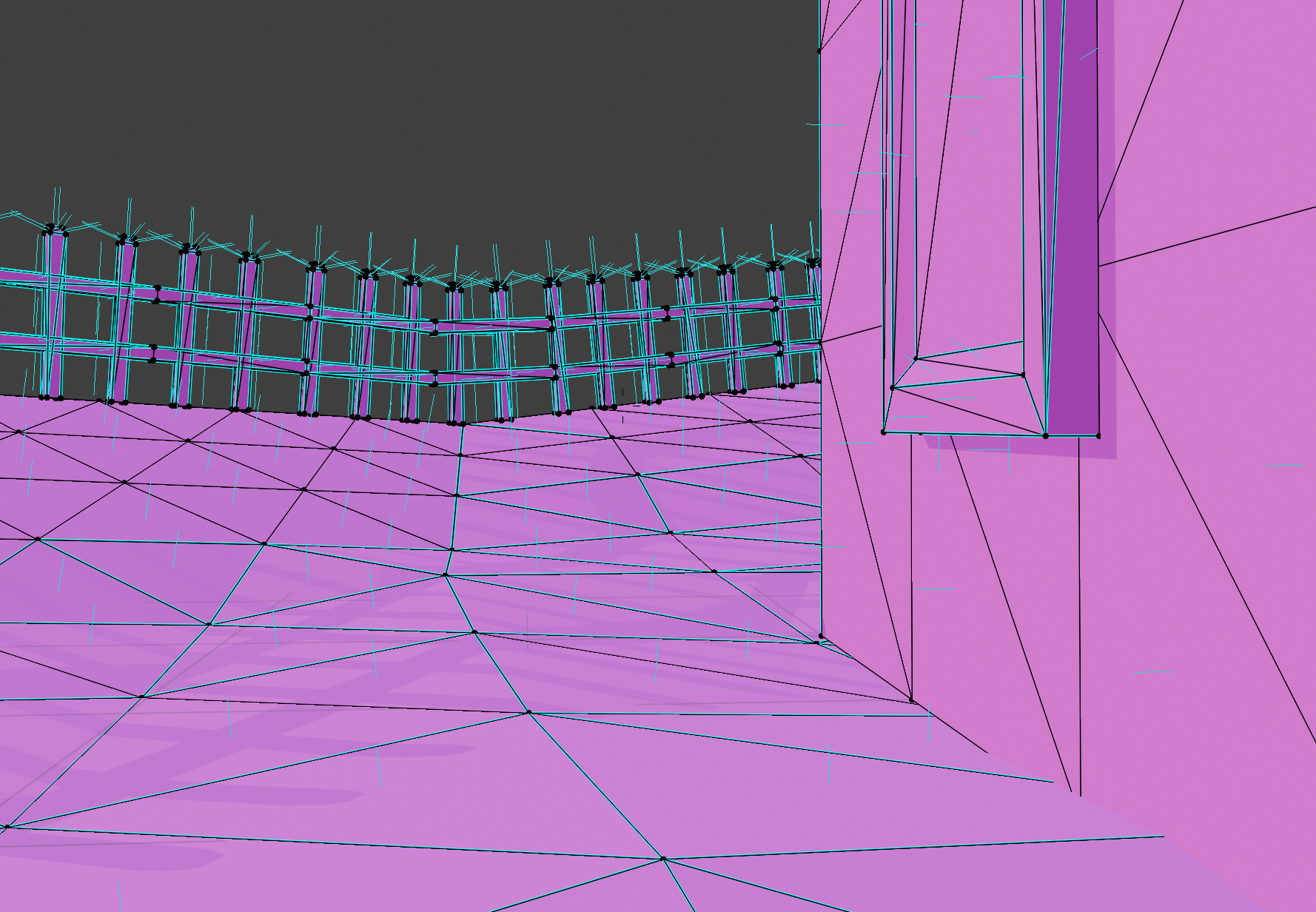
Winding order can be a bit abstract. Many 3D modelling applications allow you to toggle the visibility of surface normals. Above shows a scene in Blender with visible surface normals toggled as short visible perpendicular lines. The normal is calculated using the dot product formula we used to find triangle area. When an object is exported, Blender or Maya or whatever package you are using will list the vertices of the triangles in counter-clock wise order from the perspective of the surface normal. This allows anyone reading the exported model to calculate the correct normal based only on the winding order of the vertices. It may be that you import an object and all of the normals are inverted and pointing in the opposite direction, and Blender and other software have tools to recalculate and flip all of the normals. CCW winding is just by convention, but it is an industry standard.
There are several other related issues that complicate an understanding of winding order, which I’ll just mention and we’ll clarify further later. For one, along with winding order every 3D engine has to be specific about the coordinate system it’s working with. We’ve mentioned that we’re using a screen space coordinate system with y values increasing downwards and x values increasing to the right. If we flip to having y increase upwards, the sign of the cross product will flip also. You might wonder why the area we calculated in crossProductZ is negative for visible triangles. If we interpret y as increasing upwards, crossProductZ would be positive for visible triangles. The sign of the cross product is therefore determined by the signs of the x and y values we’re using in this way.
Another issue that is closely related is called the handed-ness of the coordinate system. There are two possible types of coordinate systems, which you’ll hear referred to as right-handed or left-handed. We don’t need to worry about this yet until we start using the third z dimension of vectors more. For now, it’s enough to grasp the distinction of giving coordinates in y up or y down space, and that the cross-product formula is used to determine the direction of the surface normal for a triangle. And finally that convention tells us that we should interpret the winding order of a triangle in CCW order when viewing the triangle from the normal facing direction.
Where are we now
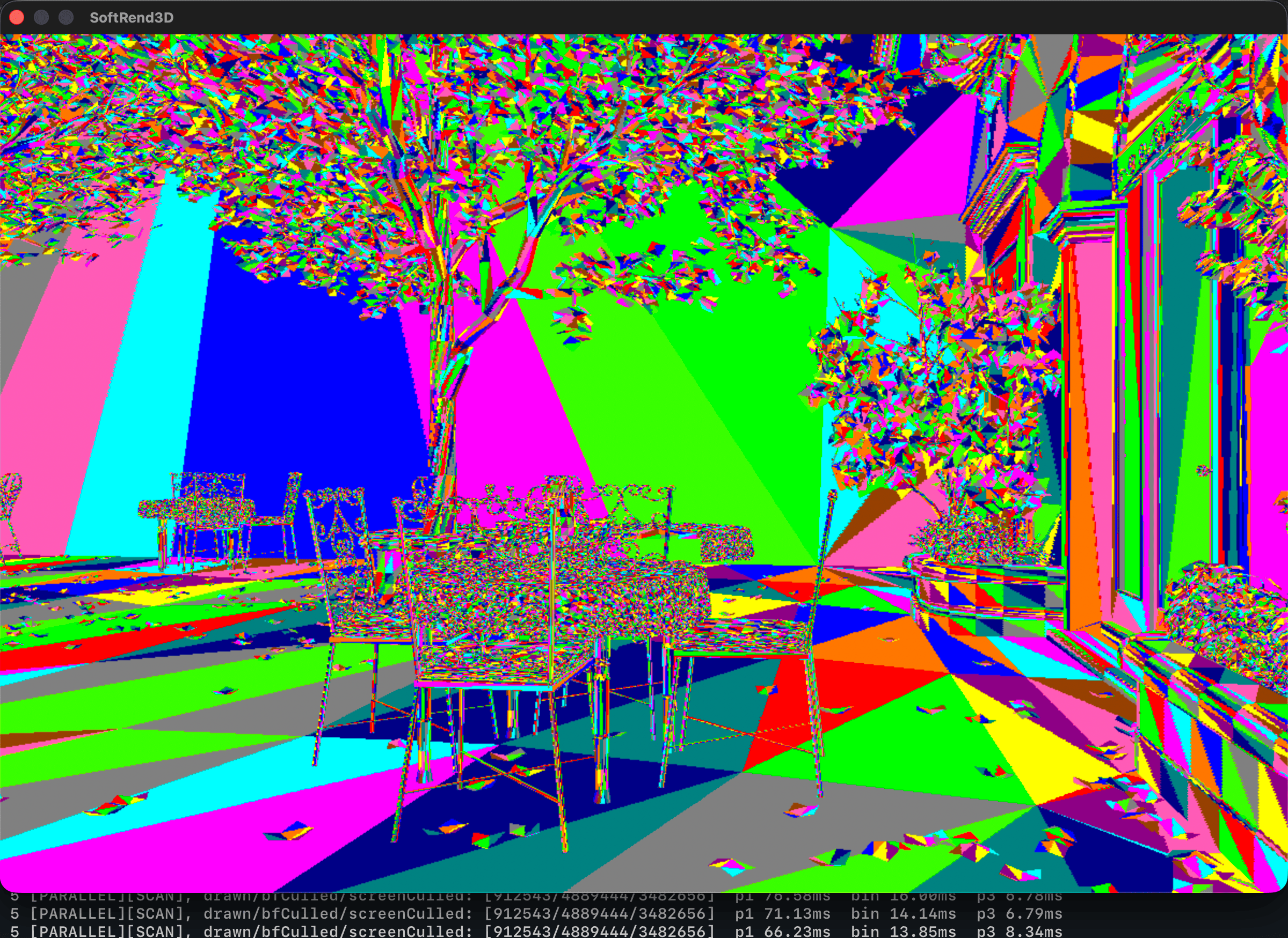
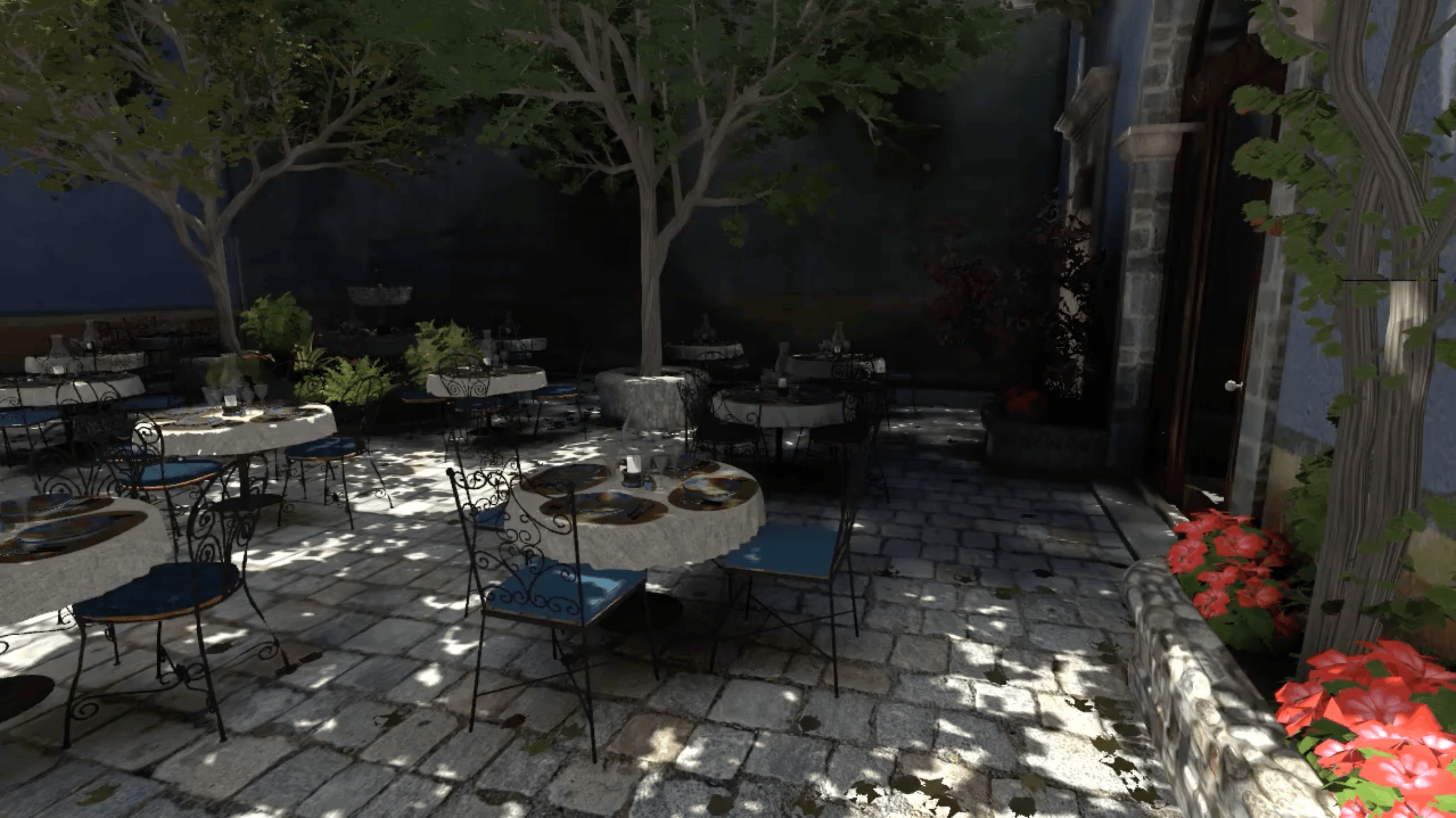
At this point, we have the basic building blocks of a 3D renderer. We could manually describe all of the triangles in a static scene just as we’ve done with this handful of triangles, or load them from a 3D model file, and apply this kind of triangle fill shading to each triangle with a single manually specified RBG color and render millions of triangles to draw an image from your favorite modern video game. The complexity of a 3D engine comes from dynamically changing that view, moving the camera around the scene, applying positional transformations to those triangles, determining their draw order and which triangles to avoid drawing, as well as lighting and texturing them and a host of other possible operations. Below is a comparison of the current version of my engine with unlit textures on a 10 million triangle scene to an OpenGL version of the San Miguel scene by Guillermo Llaguno. Theoretically we could implement mesh loading from a file where triangle and vertex has been placed to simulate perspective distortion and scene depth relative to the viewer, and then render this image just by iterating over every triangle and using the drawTriangle function as we’ve implemented it. But as soon as we attempt to implement camera movement the illusion will break. We’d lose the perspective distortion and the depth accuracy of the triangles and it would turn in to a mess of random colors and lines. There’s still a lot of machinery left that needs to be implemented to get us to handle moving around the scene.
Final notes
drawLine is now dead code that is not called anywhere, but we’ll keep it around for now. You never know when we’ll want to draw a line.
Further note on vectors as positional vs. displacement
Some mathematicians or programmers might turn their nose up at referring to our triangle points as vectors. They’ll say a vector doesn’t encode position, just a length (magnitude) and angle. I would say that in the context we’re using vectors, the distinction doesn’t really matter. In our cross product video above, triangle point c at (2, 4) in the top left is described from the origin, moving up four and right two units. It can also be described as a displacement from a represented with the vector v = (1, 3), moving up three and right 1 from point a.
As I mentioned earlier, we could have treated a, b and c as vectors and chosen two of them to plug into our cross product formula, but we would have gotten a triangle with the origin at (0, 0) as one of its points. You can think of a triangle in terms of the edges that enclose it. Vectors u and v enclose the triangle abc while vectors b and c for example enclose triangle Obc if we label the origin as O. The reason we calculate u and v is so that all three of the triangle positions are encoded into two vectors.
You might see a hidden danger. What if we keep u and v around as vectors u = (3, 0) and v = (1, 3) and lose the context that these are displacement vectors and not absolute Cartesian positions? Nothing stops this from happening, so we’ll have to take care to never use displacement vectors to represent absolute position.
Code fixes
Header #include issue
I just realized that the clang compiled on macOS includes the C standard library headers by default. There are a few headers we need to explicitly include for cross platform compatibility. fenster.h also pulls in some of these, but just to be explicit:
#include <stdint.h>  // uint32_t, int64_t types
#include <stdbool.h> // bool
#include <limits.h>  // INT_MIN/MAX defines (from compiler built-ins, -2147483648 to 2147483647)
#include <stdlib.h>  // abs()
#include <stdio.h>   // printf()

#include "../include/fenster.h"
Updated drawTriangle() comment
// Draws the triangle filled with the ARGB format value in color. Triangles with
// 0 area (degenerate) are skipped. Calls crossesScanlineAt for each triangle
// edge to find if and where it crosses the current scanline, then fills
// between those edges if they exist.
// TODO: Calculate slope for each edge once and pass to crossesScanlineAt()
void drawTriangle(const Vec2 *tri, uint32_t color) {
Timing code
        // Time since last FPS print
        int64_t elapsedMS = fenster_time() - secondStartMS;
        if (elapsedMS >= 1000) {
            printf("fps: %.1f\n", frameCount * 1000.0f / elapsedMS);
            frameCount    = 0;
            secondStartMS = fenster_time();
        }
In main when we calculate the FPS every second, we multiply frameCount by 1000.0f which promotes the result to a single precision float, then divides the numerator by elapsedMS which promotes the calculation to a double. This has no effect and isn’t technically a bug, the same value is printed either way, but it’s good to point out to be careful to notice when the compiler promotes between float and double values. We handle it properly below with nextFrameTime += 1000.0 / FPS; which maintains double precision through the whole calculation. Here is the corrected version:
printf("fps: %.1f\n", frameCount * 1000.0 / elapsedMS);