Clean up old timing code
We’re not going to need to print the channel values for a buffer pixel again, so we can remove that. I changed the timing code to be more accurate. We cap the renderer to the target frame rate by initializing nextFrameTime to fenster_time() and advancing it by the desired frame time (1000ms / FPS) each frame loop, sleeping until it’s reached. If the OS wakes us late, the next sleep is shortened by exactly the amount of oversleep, and if remainingMS > 0 fails the check, we don’t sleep and the next frame will also have a shorter sleep until it catches up. I also removed the unused FRAME_TIME macro. The new code at the end of main looks like:
        // Sleep until we reach desired frame time
        nextFrameTime += 1000.0 / FPS;
        double remainingMS = nextFrameTime - (double)fenster_time();
        if (remainingMS > 0) fenster_sleep(remainingMS);
    }
This still has a minor issue when our program stalls because of system thrashing. nextFrameTime falls far behind the fenster_time() clock and our rendering loop will catch-up without sleeping until it catches up. This would look like the rendering freezing followed by a rapid burst of frames rendered far quicker than our frame rate cap until remainingMS is no longer negative. An easy solution would be to clamp nextFrameTime to the the current fenster_time() when we’re more than a frame (1000 / FPS) behind. We’ll tackle this later when we actually have something substantial to process during our render loop and this becomes more visible.
Drawing our first triangle
Drawing anything to the screen at this point involves setting the color value of the individual buffer pixels. Because we declared buffer in global scope, it is automatically 0 initialized along with all other global scoped variables, which as we saw means the color black when all color channels are set to 0 in RGB. We have created a window WIDTH pixels wide and HEIGHT pixels tall, so there are 600x400 or 240,000 pixels in our window. We could have declared buffer as a row-major multi-dimensional array, uint32_t buffer[HEIGHT][WIDTH] which is of type uint32_t **, and assigned window.buf = (uint32_t *)buffer;. This simplifies the notation for element access, allowing us to access elements with buffer[y][x], but hides the flat nature of the memory array and requires us to remember the array is row major. Both forms should compile to the same machine code, so it’s mostly a matter of preference - I like using a flat array. For the flat buffer array we can create a convenience macro for getting and setting pixel information, and add a new color constant WHITE for later use:
#define FPS 60 // Targeted frame rate (frequency in hz)

// Framebuffer is row-major
#define PIXEL(x, y) buffer[(y) * WIDTH + (x)]

#define WHITE 0xFFFFFFFF

uint32_t buffer[WIDTH * HEIGHT];
This removes any concern over remembering whether we’re using row or column major ordering, or remembering how to write the indexing expression for each element.
The first step to drawing a triangle is to determine its vertices. Note that PIXEL(0, 0) that addresses our first pixel in the buffer is centered in the top-left of the screen. Y increases downwards, unlike in a standard Cartesian system where +y grows upwards. A y value of 300 is “below” a y value of 100. We’ll cover coordinate systems in more depth later, for now just note that we’re dealing with “screen space” coordinates for buffer pixel positions, with +y growing down and +x to the right.
If we want a 300 pixel wide, 200 pixel tall isosceles triangle that fits nicely in our screen, we can use the following declarations followed by calling PIXEL for each point:
        .buf    = buffer
    };

    // define's the vertices of a 300 pixel wide, 200 pixel high screen centered triangle
    int x0 = 150, y0 = 300; // bottom-left
    int x1 = 450, y1 = 300; // bottom-right
    int x2 = 300, y2 = 100; // apex
    PIXEL(x0, y0) = WHITE;
    PIXEL(x1, y1) = WHITE;
    PIXEL(x2, y2) = WHITE;

    // Open a system window using the given window specifications
    if (fenster_open(&window) < 0) return 1;
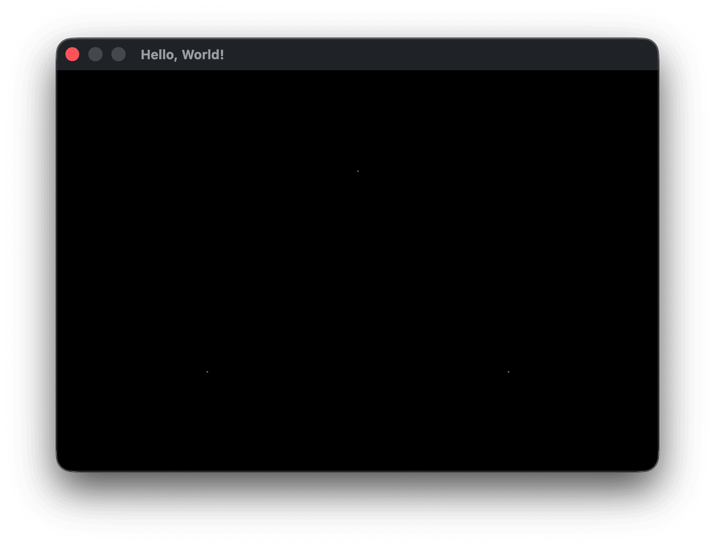
If you compile and run you should now see 3 single pixels outlining the vertices of a triangle.
How do we connect the dots between two vertices to form an edge? There are several common methods. We need to test each pixel to determine if it’s on the line. Bresenham’s line algorithm is an oldy that avoids using floating-point division, but is a bit of a black magic algorithm at first glance. For me, linear interpolation is the most understandable method for finding a given point along an edge with two known endpoints. Modern FPUs can easily handle the simple division we’ll need to use.
Linear interpolation
We have two endpoints on an edge, (x0, y0) and (x1, y1), and for any x value along that line we want to find the corresponding y.
The differences between the x and y values of the two points are shown in the video as dx and dy, the legs of the right triangle formed by the two endpoints. For any point x along the edge, a smaller similar triangle is formed with legs (x - x0) and (y - y0). Because the triangles are similar, their corresponding sides are proportional:
dy / dx = (y - y0) / (x - x0)
We want to get to a simple equation to solve for y. This is typically given as y = y0 + t * dy. By rearranging the above equation with cross multiplication:
(x - x0)/dx = (y - y0)/dy
We define t = (x - x0) / dx as the interpolation parameter — the ratio of how far x has traveled across dx, ranging from 0 at x0 to 1 at x1. Substituting t into (x - x0)/dx = (y - y0)/dy:
t = (y - y0)/dy
Multiplying t by dy scales the ratio t to the full height of the triangle, giving the displacement (distance) of y from y0:
t * dy = y - y0
Now we have the side length dy scaled by the ratio t equal to the displacement (distance) of y from y0. Adding y0 to both sides turns the formula from solving for a displacement into solving for the y coordinate:
y = y0 + t * dy
Grounding this in an example from the video, with endpoints (2, 10) and (16, 17) and x = 7 we can find y at that point using:
Solving for (x=7, y=?)
dx = 14, dy = 7
(x0, y0) = (2, 10)
t  = (x - x0) / dx = (7 - 2) / 14  = 5/14 ≈ 0.36
y  = y0 + t * dy   = 10 + 0.36 * 7        ≈ 12.5
y ≈ 12.5, so the interpolated point along the line defined (2, 10) and (16, 17) at x = 7 is (7, 12.5).
We derived the interpolation formula starting from a geometric proportion of triangle sides. Typically the formula is derived algebraically from the point-slope form of a line, y = y0 + m(x - x0), by substituting m = dy/dx and letting t = (x - x0)/dx.
One issue I had early on when just being presented with the interpolation algorithm was trying to figure out what each of the values meant, and why we added y0 to the formula, and why y0 and not y1. Hopefully this helps clarify what these values are, and you can answer those questions I had.
For example, we could use the second endpoint as our anchor resulting in different sides for our initial proportion, with (x1, y1) in place of (x0, y0) and t using (x1 - x) / dx instead of (x - x0) / dx) so that y now becomes y1 + t * dy. With the example we just gave above with the same endpoints and x value of 7:
Solving for (x=7, y=?)
dx = 14, dy = 7
(x1, y1) = (16, 17)
t  = (x - x1) / dx = (7 - 16) / 14  = -9/14 ≈ -0.64
y  = y1 + t * dy   = 17 + -0.64 * 7         ≈ 12.5
We have a new t value and anchor from y1 instead of y0, but end up with the same y value.
Drawing edges with linear interpolation
Linear interpolation is one of the most useful algorithms in graphics programming and you’ll see and use it often. It’s worth spending the effort to understand it now. Before moving on, I would recommend pausing and trying to implement the line drawing algorithm to draw a triangle by yourself before reading my version.
My first naive attempt looked like this:
void drawLine(int x0, int y0, int x1, int y1, uint32_t color) {
    int dx = x1 - x0, dy = y1 - y0;

    for (int x = x0; x <= x1; x++) {
        float t = (float)(x - x0) / dx; // progress along x: 0 at leftX, 1 at rightX
        int y = (int)(y0 + t * dy);     // interpolated y at this x
        PIXEL(x, y) = color;
    }
}
I put the drawLine definition just before main, and in main at the top I defined a few vertices and attempted to draw a triangle by calling drawLine three times to draw the three edges:
        .buf    = buffer
    };

    // vertices of a 100 pixel wide, 300 pixel tall screen centered triangle
    int x0 = 250, y0 = 350; // bottom-left
    int x1 = 350, y1 = 350; // bottom-right
    int x2 = 300, y2 =  50; // apex

    drawLine(x0, y0, x1, y1, WHITE);
    drawLine(x1, y1, x2, y2, WHITE);
    drawLine(x2, y2, x0, y0, WHITE);
This just draws a straight horizontal line. Thinking it over, what happens when it draws the second edge drawLine(x1, y1, x2, y2, WHITE)?
dx becomes -50, dy becomes -300, and in the first iteration of the for loop x is set to 350 and immediately fails the x <= x1 test because x1 is 300, so that edge never gets drawn. Similarly, the third edge drawLine(x2, y2, x0, y0, WHITE) never draws because x is set to 300 and fails x <= x1 because x1 is 250. So the only edge that gets drawn is drawLine(x0, y0, x1, y1, WHITE) as a 100 pixel wide horizontal line.
The fix is easy, we just need to make sure that we start iterating from the leftmost x to the rightmost inside drawLine:
    int dx = x1 - x0, dy = y1 - y0;

    int leftX = x0, rightX  = x1;

    if (x0 > x1) { leftX = x1; rightX  = x0; }

    for (int x = leftX; x <= rightX; x++) {
        float t = (float)(x - leftX) / dx; // progress along x: 0 at leftX, 1 at rightX
        int y = (int)(y0 + t * dy);        // interpolated y at this x
        PIXEL(x, y) = color;
    }
Now I get a bus error on my machine. Looks like we tried to access an out of bounds pixel. Adding a debuf print to the loop we can find where:
        int y = (int)(y0 + t * dy);
        printf("PIXEL(%d, %d)\n", x, y);
        PIXEL(x, y) = color;
The first edge draws correctly from (250, 350) to (350, 350), the second edge is where we crash:
PIXEL(300, 350)
PIXEL(301, 356)
PIXEL(302, 362)
PIXEL(303, 368)
PIXEL(304, 374)
PIXEL(305, 381)
PIXEL(306, 387)
PIXEL(307, 393)
PIXEL(308, 399)
PIXEL(309, 405)
[1]    46141 bus error  ./softrend
Our screen is 400 pixels tall and we tried to write to y = 405, which would be below the screen. But we want to be drawing from an apex y position at 50 down to the base horizontal line y position at 350. When x0 > x1 we failed to swap the y values also and we lost the relative positioning of y with respect to x. In other words, we changed the line’s endpoint positions from (350, 350) and (300, 50) to (300, 350) and (350, 50). Easy fix, we’ll add a similar swap for y.
void drawLine(int x0, int y0, int x1, int y1, uint32_t color) {
    int dx = x1 - x0, dy = y1 - y0;

    int leftX = x0, rightX  = x1;
    int topY  = y0, bottomY = y1;

    // Swap both x and y together to preserve the endpoint pairing —
    // topY must be the y value at leftX, not rightX, or t interpolates
    // in the wrong direction.
    if (x0 > x1) {
        leftX = x1; rightX  = x0;
        topY  = y1; bottomY = y0;
    }

    for (int x = leftX; x <= rightX; x++) {
        float t = (float)(x - leftX) / dx; // progress along x: 0 at leftX, 1 at rightX
        int y = (int)(topY + t * dy);      // interpolated y at this x
        PIXEL(x, y) = color;
    }
}
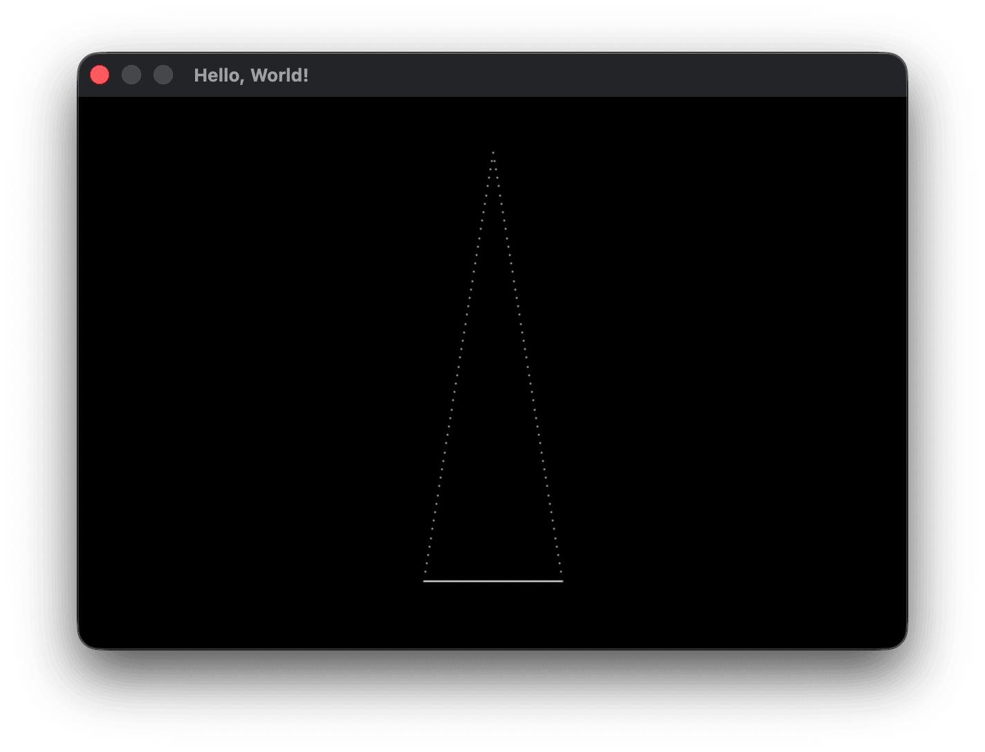
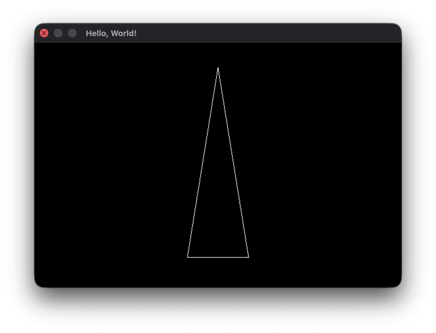
That’s odd. It looks like a triangle now, but there are a bunch of gaps in the vertical line. If you noticed the debug pixel position values, x was incremening by 1 but y was skipping 6 or 7 pixels each iteration. That’s where the vertical gaps are coming from. How do we fix this? The difference in x values is 100 and the difference in y values is 300. If we iterated over the range of y values (300 times) we should see the interpolated x values increase after 6 or 7 iterations. We want to loop over the dominant axis with the greatest difference (length) and interpolate the positions of the other minor axis.
void drawLine(int x0, int y0, int x1, int y1, uint32_t color) {
    int dx = abs(x1 - x0), dy = abs(y1 - y0);

    // Sort by the dominant axis
    // x-dominant: ensure leftX < rightX
    // y-dominant: ensure topY < bottomY
    // x and y must swap together — a partial swap mixes coordinates between the endpoints
    int xDominant = (dx >= dy);
    int leftX = x0, rightX  = x1;
    int topY  = y0, bottomY = y1;
    if (xDominant ? leftX > rightX : topY > bottomY) {
        leftX = x1; rightX  = x0;
        topY  = y1; bottomY = y0;
    }

    if (xDominant) {
        for (int x = leftX; x <= rightX; x++) {
            float t = (float)(x - leftX) / dx; // progress along x: 0 at leftX, 1 at rightX
            int y = (int)(topY + t * dy);      // interpolated y at this x
            printf("PIXEL(%d, %d)\n", x, y);
            PIXEL(x, y) = color;
        }
    } else {
        for (int y = topY; y <= bottomY; y++) {
            float t = (float)(y - topY) / dy; // progress along y: 0 at topY, 1 at bottomY
            int x = (int)(leftX + t * dx);    // interpolated x at this y
            printf("PIXEL(%d, %d)\n", x, y);
            PIXEL(x, y) = color;
        }
    }
    printf("\n");
}
This got rid of the gaps on the second edge from (300, 50) to (350, 350) for the drawLine(x1, y1, x2, y2, WHITE) call, but it printed that side twice. If you look at the third edge called with drawLine(x2, y2, x0, y0, WHITE), the debug printing shows its x values also increasing from (300, 50) to (350, 350), just like the second edge. We computed the dx value from the absolute difference of x1 - x0, but doing so lost the sign of dx. If we’re drawing the edge starting from (300, 50) and ending at (250, 350) then the difference between leftX and rightX is -50, not 50 in the !xDominant branch. When we swap x and y positions, the sign of the opposite axis’s difference becomes stale and needs to be recalculated. Also, we took the absolute value of each difference to be able to compute the dominant axis with dx >= dy. For both reasons we need to recompute the minor-axis’ delta from the sorted endpoints to get the correct line direction. We can add a line to each branch doing this:
    if (xDominant) {
        dy = bottomY - topY; // recompute minor-axis delta from the sorted endpoints
        for (int x = leftX; x <= rightX; x++) {
            float t = (float)(x - leftX) / dx; // progress along x: 0 at leftX, 1 at rightX
            int y = (int)(topY + t * dy);      // interpolated y at this x
            printf("PIXEL(%d, %d)\n", x, y);
            PIXEL(x, y) = color;
        }
    } else {
        dx = rightX - leftX; // recompute minor-axis delta from the sorted endpoints
        for (int y = topY; y <= bottomY; y++) {
            float t = (float)(y - topY) / dy; // progress along y: 0 at topY, 1 at bottomY
            int x = (int)(leftX + t * dx);    // interpolated x at this y
            printf("PIXEL(%d, %d)\n", x, y);
            PIXEL(x, y) = color;
        }
    }
Now the third edge properly draws down and to the left from the apex to the bottom left vertex, and the pixel gaps on the minor axis edges are gone. There are a few edge case concerns to think about. What if our t calculations divide by a dx or dy that is 0? Can this happen? It turns out only in one case. Can you spot it?
When both dx and dy are 0, we have a degenerate edge where both vertices are the same. In this case, we end up on the xDominant branch and divide by dx that is equal to 0 which we want to avoid. We want to handle this edge case by just printing a single pixel at (x0, y0) or (x1, y1) - it doesn’t matter which. Add this to the top of drawLine:
    int dx = abs(x1 - x0), dy = abs(y1 - y0);
    // Degenerate case: both endpoints identical, draw a single pixel and bail
    // dx == 0 alone is not sufficient — a vertical line has dx == 0 but dy > 0
    // and draws correctly via the y-branch.
    if (dx == 0 && dy == 0) { PIXEL(x0, y0) = color; return; }
Click here for the current main.c
drawLine edge case testing
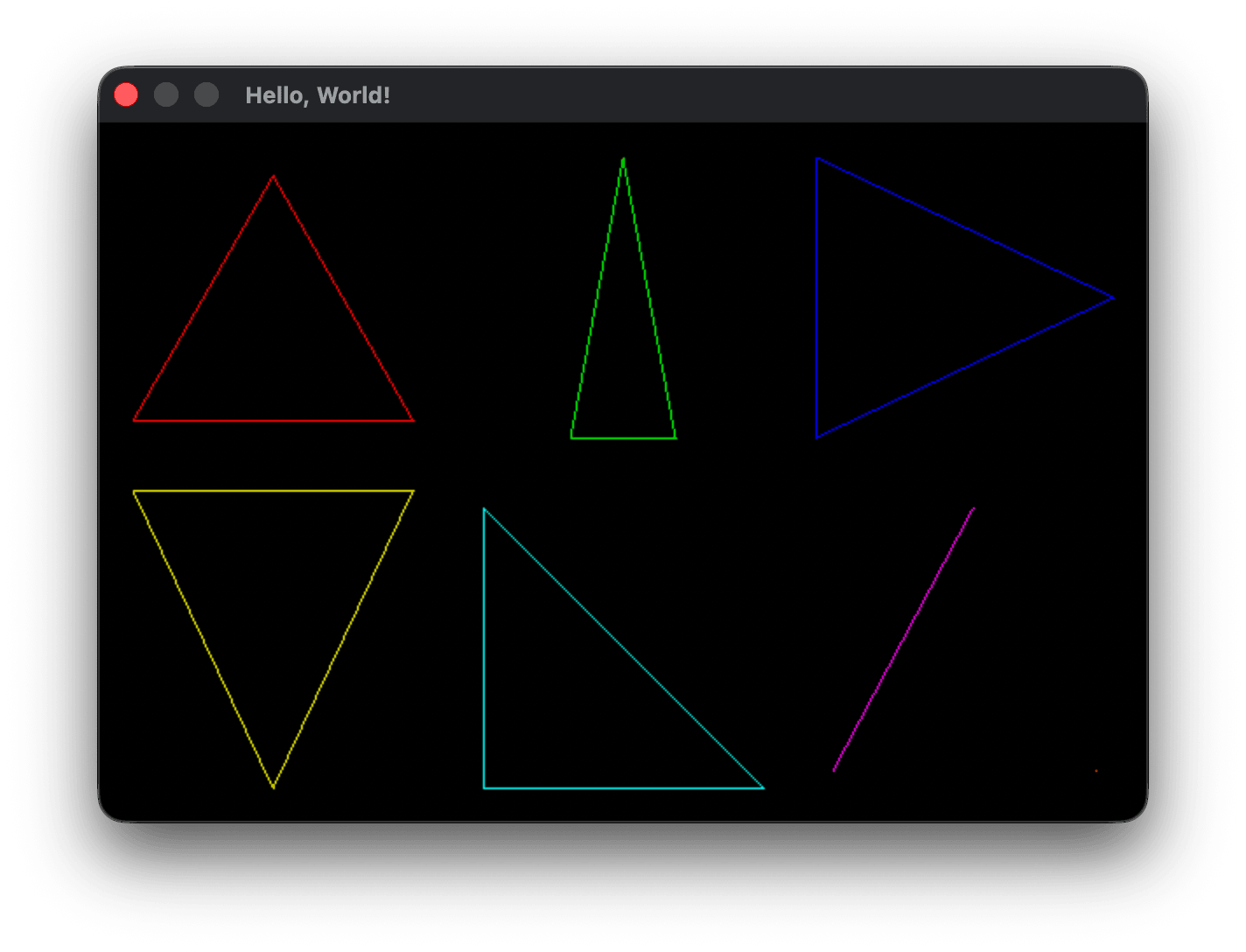
drawLine should now handle all types of lines cleanly, but it’s best to check. If we divide the screen up into a 3x2 grid and put a triangle in each, we can fit six example triangles on the screen at once. We’re also going to want more colors in the future, so I created an array of color values colors and an enum Color to index them. Place this where we currently have the #define for WHITE:
typedef enum {
    BLACK, WHITE, RED, GREEN, BLUE,
    YELLOW, CYAN, MAGENTA,
    GRAY, SILVER,
    ORANGE, PURPLE, MAROON, NAVY, TEAL,
    COLOR_COUNT
} Color;

uint32_t colors[] = {
    0xFF000000, // BLACK
    0xFFFFFFFF, // WHITE
    0xFFFF0000, // RED
    0xFF00FF00, // GREEN
    0xFF0000FF, // BLUE
    0xFFFFFF00, // YELLOW
    0xFF00FFFF, // CYAN
    0xFFFF00FF, // MAGENTA
    0xFF808080, // GRAY
    0xFFC0C0C0, // SILVER
    0xFFFF8000, // ORANGE
    0xFF800080, // PURPLE
    0xFF800000, // MAROON
    0xFF000080, // NAVY
    0xFF008080, // TEAL
};
Replace the x0/x1/x2 etc. assignments and the three single drawLine calls with:
    // x-dominant (wide/flat)        — top-left cell
    drawLine( 20, 170, 180, 170, colors[RED]);
    drawLine(180, 170, 100,  30, colors[RED]);
    drawLine(100,  30,  20, 170, colors[RED]);

    // y-dominant (tall/narrow)      — top-middle cell
    drawLine(270, 180, 330, 180, colors[GREEN]);
    drawLine(330, 180, 300,  20, colors[GREEN]);
    drawLine(300,  20, 270, 180, colors[GREEN]);

    // one vertical edge              — top-right cell
    drawLine(410,  20, 410, 180, colors[BLUE]);
    drawLine(410, 180, 580, 100, colors[BLUE]);
    drawLine(580, 100, 410,  20, colors[BLUE]);

    // one horizontal edge            — bottom-left cell
    drawLine( 20, 210, 180, 210, colors[YELLOW]);
    drawLine(180, 210, 100, 380, colors[YELLOW]);
    drawLine(100, 380,  20, 210, colors[YELLOW]);

    // right triangle                 — bottom-middle cell
    drawLine(220, 220, 220, 380, colors[CYAN]);
    drawLine(220, 380, 380, 380, colors[CYAN]);
    drawLine(380, 380, 220, 220, colors[CYAN]);

    // two coincident vertices        — bottom-right cell
    drawLine(500, 220, 500, 220, colors[MAGENTA]);
    drawLine(500, 220, 420, 370, colors[MAGENTA]);
    drawLine(420, 370, 500, 220, colors[MAGENTA]);

    // single point — tucked in corner of bottom-right cell
    drawLine(570, 370, 570, 370, colors[ORANGE]);
    drawLine(570, 370, 570, 370, colors[ORANGE]);
    drawLine(570, 370, 570, 370, colors[ORANGE]);
Key handling
Soon we’ll be needing more complex keyboard and mouse input handling, but for now, I just want to add the Escape key and Command+Q/Ctrl+Q for closing the program.
Fenster keyhandling minutiae
You can safely skip this section if you don’t want a quick look at the gory details of how Fenster handles keyboard input on macOS in particular, but I was curious so here’s what I discovered. Fenster stores key presses retrieved from the OS event loop in int keys[256] and int mod declared in the fenster struct (the type of our window value) in fenster.h. Each platform layer has its own FENSTER_KEYCODES array. On macOS it is:
static const uint8_t FENSTER_KEYCODES[128] = {65,83,68,70,72,71,90,88,67,86,0,66,81,87,69,82,89,84,49,50,51,52,54,53,61,57,55,45,56,48,93,79,85,91,73,80,10,76,74,39,75,59,92,44,47,78,77,46,9,32,96,8,0,27,0,0,0,0,0,0,0,0,0,0,0,0,0,0,0,0,0,0,0,0,0,0,0,0,0,0,0,0,0,0,0,0,0,0,0,0,0,0,0,0,0,0,0,0,0,0,0,0,0,0,0,0,0,0,0,0,0,0,0,0,26,2,3,127,0,5,0,4,0,20,19,18,17,0};
macOS returns these virtual hardware key codes for each key, such as 0 for ‘A’, 10 for ‘B’, 8 for ‘C’ - in other words, not in ASCII order. Escape is 53, Command (CMD) is 55, left control is 59. When Fenster reads a key press or release event it runs inside fenster_loop:
NSUInteger k = msg(NSUInteger, ev, "keyCode");
f->keys[k < 127 ? FENSTER_KEYCODES[k] : 0] = evtype == 10;
NSUInteger mod = msg(NSUInteger, ev, "modifierFlags") >> 17;
f->mod = (mod & 0xc) | ((mod & 1) << 1) | ((mod >> 1) & 1);
k stores the macOS virtual key code, and the keys indexing expression k < 127 checks that the keycode is between 0-126 so we don’t index into a non-existant FENSTER_KEYCODES element. The ternary expression returns the ASCII code in FENSTER_KEYCODES or 0 if k is out of bounds. That keys element is then set to 1 if evtype is 10 or 0 otherwise. When evtype is 10 it indicates the key is being held, and 11 means not being held. An example helps clarify this. If the escape key (mac key code 53) is pressed, Fenster sets f->keys[FENSTER_KEYCODES[53]] which is f->keys[27] to 1. If escape is released that value is cleared to 0. Worth noting Fenster only tracks alphabetic letters using the upper case ASCII codes 65-90, it’s up to us to interpret if they’re upper case or not depending on if the shift modifier is held, or if we want to extend Fenster to handle other capabilities like tracking whether caps-lock is on.
mod stores the modifier keys as bit flags. Fenster performs a bit shift to place bits 17-20 down to 0-3. Bit 0 is shift, bit 1 is control, bit 2 is opt/alt and bit 3 is command. Outside of macOS, most toolkits and applications place control as the lowest modifier bit, so Fenster swaps the order of bits 0 and 1 so that control is in bit 0 and shift in bit 1 (((mod & 1) << 1) and ((mod >> 1) & 1)) and keeps bits 2 and 3 the same (mod & 0xc), logical or’ing the bits together. If <Cmd+Q> is pressed, f->keys['Q'] is 1 and f->mod is 8 (corresponding to only bit 3 being set to 1).
We can define a function handleInput to take our window value and read the current key presses, returning whether the application should should stay open (0) or close (1). I placed the definition right before main:
// Returns 1 if the application should quit, 0 otherwise
int handleInput(struct fenster *f) {
    if (f->keys[27]) return 1;                        // Escape
    if (f->keys['Q'] && (f->mod & 8)) return 1;      // Cmd+Q  (macOS)
    if (f->keys['Q'] && (f->mod & 1)) return 1;      // Ctrl+Q (Windows/Linux)
    return 0;
}

int main()
and in main:
            secondStartMS = fenster_time();
        }

        if (handleInput(&window)) break;

        // sleep until we reach desired FRAME_TIME
        nextFrameTime += 1000.0 / FPS;
Bug fixes
Unused frame timing variable
I noticed that frameStartMS declared at the top of the while loop in main is not doing much lifting. I might need such a variable later, but for now we can remove its declaration and change the FPS check loop to use fenster_time() directly in both cases to grab the current and not stale system time:
        // Time since last FPS print
        int64_t elapsedMS = fenster_time() - secondStartMS;
        if (elapsedMS >= 1000) {
            printf("fps: %.1f\n", frameCount * 1000.0f / elapsedMS);
            frameCount    = 0;
            secondStartMS = fenster_time();
        }
drawLine comment
It’s good to always keep your comments up to date. Since this is an educational codebase, comments will err on the side of overly verbose. I like to comment my functions at the top with any relevant information on the function in general. To the drawLine definition I added a performance related TODO for the future:
// Draw a straight line from one endpoint in the buffer to another
// Does not do bounds checking - up to the caller to pass valid indices
// TODO: for performance we can switch to Bresenham's later if needed
//       or use point-slope and cache slope once as dy/dx and using
//       y = topY + (x - leftX) * slope for each pixel
void drawLine(int x0, int y0, int x1, int y1, uint32_t color) {
frameTime sleep comment
At the top of the lesson we talked about adding a TODO comment to the frame sleep code at the end of the render loop in main. TODO is a common keyword that most syntax highlighters will highlight so the comment stands out.
        // Sleep until we reach desired frame time
        // TODO: if nextFrameTime falls far behind due to program stall, clamp it
        //       forward instead of spinning no-sleep frames to catch up
        nextFrameTime += 1000.0 / FPS;
        double remainingMS = nextFrameTime - (double)fenster_time();
        if (remainingMS > 0) fenster_sleep(remainingMS);
    }
drawLine rounding issue
Our linear interpolating algorithm branches to solve for a given x or y value on the line depending on which axis is more dominant. In both cases, the resulting value is stored as an integer from a floating point calculation. Remember that positive floats are integer cast the resulting value is floored towards 0 and negative values are rounded up towards 0. In the example above with endpoints (2, 10) and (16, 17) and x = 7 we can find y at that point using:
dx = 14, dy = 7
(x0, y0) = (2, 10)
t  = (x - x0) / dx = (7 - 2) / 14  = 5/14 ≈ 0.36
y  = y0 + t * dy   = 10 + 0.36 * 7        = 12.5
y is floored from 12.5 to 12. If we want a more accurate pixel value, we can add 0.5 to both branch calculations:
// x dominant
int y = (int)(topY + t * dy + 0.5f); // interpolated y at this x, rounded
// y dominant
int x = (int)(leftX + t * dx + 0.5f); // interpolated x at this y, rounded
Because the example slope is 1/2, the fractional pixel positions will always be exactly at a .5 value and rounded up. For lines with a steep or shallow slope, the effect is more pronounced. For example, for a different line where x is 7, t is 0.7 and y0 is 0, then y will be 4.9. Adding .5 to y gives 5.4, and the integer truncation changes it to 5, which is far closer to the true position than the 4 it would have been. At 4.9 the integer flooring is off by 0.9 pixels, but rounding is only off by 0.1 pixels. Rounding buys us more accurate pixel positioning, with the greatest improvement when the fractional part of y (or x, depending on the dominant axis) is large.
Applying the rounding to our multiple triangles example, it’s hard to see the difference unless you flip between the triangles both with and without rounding, but the interpolation with rounding is more accurate. You’ll see a slight shift in the position of the triangles relative to the window border, and within each triangle a slight shift in the pixel positioning. It doesn’t make the sides appear any straighter, it’s just that some pixels are in a more accurate position. The .gif below shows the triangles with edge lerping with rounding first, then without.